
Polish law requires the development of a fire scenario tailored to a given building. The fire scenario is one of the elements of the building design, essential for the construction process.
In this article, we examine the fire scenario from several perspectives — from legal requirements, through the expert’s description and the designer’s control table, to the automation specialist’s control matrix and the building user’s fire safety instructions. At each of these stages, the fire scenario takes a different form and level of detail, and only together do all these perspectives form a coherent whole.
Legal Requirements
The Regulation of the Minister of Development of 11 September 2020 on the detailed scope and form of the building design divides the building design into four main parts:
- the site development plan (PZT),
- the architectural and construction design (PAB),
- the technical design (PT),
- annexes (opinions, arrangements, permits, statements on road connectivity, health and safety information).
To obtain a building permit, the site development plan (PZT) and the architectural and construction design (PAB) are required. The technical design (PT) is not submitted to the authority issuing the permit — it is submitted later to the construction supervision along with documents for occupancy notification.
For the purpose of construction, a detailed design (PW) is prepared as an extension and elaboration of the building design. It contains the necessary detailed information for carrying out work on site.
All of the above-mentioned designs are divided into discipline-specific designs — most commonly architecture, structural engineering, sanitary installations, and electrical installations.
Fire safety information is distributed across all parts of the building design: the site development plan, the architectural and construction design, and the technical design, progressing from general to specific.
For the fire automation specialist, the most relevant element of the building design is the technical design. It contains the basic information enabling the implementation of a fire automation system in a given building, primarily:
- information on the division into fire zones and smoke zones,
- information on evacuation conditions and strategy,
- information on fire protection devices and other safety installations,
- information on adopted fire scenarios,
- information on preparing the building for rescue operations.
If the technical design does not contain sufficient information about fire protection devices, an additional fire protection device design will need to be prepared.
Definition of a Fire Scenario
The regulation (Dz.U. 2023 item 1563 §2.4) defines a fire scenario as:
“A fire scenario means a description of the sequence of possible events during a fire, representative of a given location or area of impact, in particular a fire zone or smoke zone, taking into account primarily: a) the functioning of fire protection devices, other technical fire protection measures, utility and technological installations and devices, and their interaction, b) organizational solutions necessary for the proper functioning of designed protections.”
Both the building design and the fire protection device design must be formally agreed upon. Agreement takes place between the designer and the fire protection expert and involves:
- consultation on design solutions for compliance with fire protection requirements,
- exchange of comments and positions regarding designed technical fire protection measures,
- development of a fire scenario for the building or its part constituting a separate fire zone.
The Expert — Scenario Description
The fire protection expert develops the fire scenario for the building. This is a document in the form of a textual description covering various aspects of the designed building. It should contain a basic description of the building and all data related to fire safety.
The scenario includes elements such as:
- general building characteristics: location, technical data, height classification, purpose and use,
- fire classification: fire resistance class, categories of human hazard, fire load density,
- estimated maximum number of people in the building,
- division into fire zones,
- internal utility installations,
- fire protection installations and devices — basic data and technical parameters,
- possible causes of fire,
- types of alarms generated by the fire alarm system,
- basic procedures during a fire alarm,
- description of fire protection device control in response to a fire alarm,
- any manually controlled systems and devices,
- conditions for proper system maintenance.
Which Devices Should Be Included?
The goal of fire protection is to meet fundamental requirements: enabling safe evacuation, limiting the spread of fire, and ensuring access for rescue teams. The primary devices include: fixed and semi-fixed extinguishing systems, fire alarm systems, emergency lighting, hydrants, fire pumps, fire dampers, smoke exhaust systems, smoke curtains, fire doors and gates, fire disconnectors, and rescue elevators.
It should be noted that this is an open list — there may be other systems and devices performing fire protection functions not explicitly listed. A simple example is passenger elevators — ensuring safe evacuation requires disabling elevator use while also verifying that no one remains inside. This often requires sending all cars to a designated level and leaving the doors open.
Similarly, escalators and moving walkways — although not classified as evacuation routes or fire protection devices, they are controlled during a fire alarm. In some cases, such as metro buildings, they may be treated as evacuation routes.
Example Scenario Description
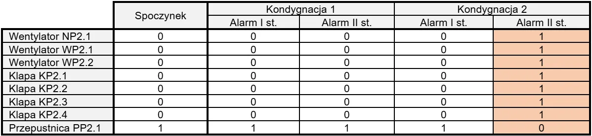
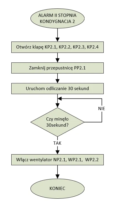
Below is an example of control description in response to a Level II fire alarm in a fire zone on floor 2:
- fire detection by the fire alarm system (automatic — sensor signal — Level I fire alarm), 15 s to confirm the alarm at the fire alarm panel,
- verification of whether the alarm is false by building staff — verification time: 3 minutes from alarm confirmation,
- if no cancellation signal is received, a Level II fire alarm is triggered.
As a result of a Level II fire alarm, the following actions occur:
- shutdown of mechanical ventilation systems in the above-ground part of the building,
- closure of fire dampers on ventilation ducts,
- immediate transmission of fire signal to the State Fire Service Command Post,
- activation of overpressure mechanical ventilation in stairwells,
- activation of overpressure ventilation in elevator shafts,
- all passenger elevators descend to the evacuation level with doors locked open,
- activation of fire ventilation on the hotel corridor of the affected floor,
- closure of smoke-tight doors held open by electromagnetic holders,
- release of access control systems on evacuation doors,
- activation of strobe optical indicators on floor 2,
- shutdown of commercial public address systems,
- activation of the voice alarm system (DSO),
- stopping of revolving entrance doors.
The Designer — Control Table
At the design stage, the designer selects specific solutions — fire protection devices and systems — that meet the requirements of the relevant fire protection regulations.
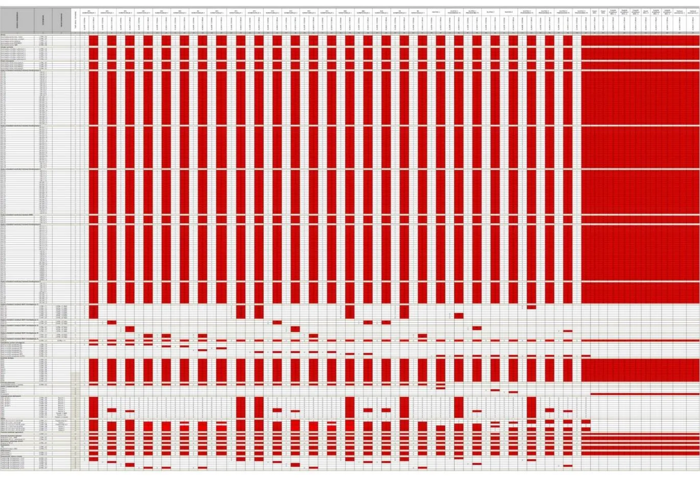
Control table
A small fragment of the control table — one sentence from the fire scenario
A control table is a document that shows, in a two-dimensional table format, the relationship between a specific actuating device (e.g., a fire damper) and fire alarms in different fire and smoke zones. Typically, columns represent fire zones while rows represent devices. At the intersection, the required device state in response to a fire alarm is entered.
Advantages of the control table:
- device states during a fire can be easily defined and presented,
- the table can be printed for on-site work and verification,
- a paper copy is a document that can be signed and stamped.
Disadvantages of the control table:
- no single accepted standard for table preparation,
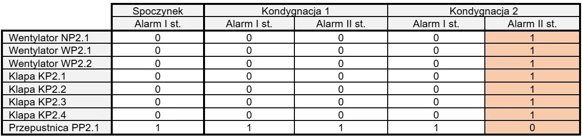
- the table reflects static device states (standby and post-activation) without temporal dependencies,
- no information on how devices transition between states,
- no information on reverse control (restoring standby state).
Control table – the starting point for the fire automation specialist
Nevertheless, the control table is the starting point for the fire automation specialist’s work on the fire scenario.
The Automation Specialist — Control Matrix
The fire automation specialist receives the control table from the designer, which indicates the required device and system states during and outside a fire alarm.
An analogy would be a train timetable — a traveler can see that a train departs from Gdynia Główna at 10:55 and ends its route in Zakopane at 21:09. But between those times, the train stops at 38 stations, with varying stop durations, connections, and priority considerations. Everything must be appropriately planned and executed.
Simple control algorithm — direct implementation of fire scenario and control table
Similarly, the fire automation specialist must implement the fire scenario assumptions at the device level. If the expert described a dependency — “device A is activated first, then device B after 60 seconds” — that is exactly how it must be implemented. The control table does not contain information about temporal dependencies — both devices are listed as “activated,” which is why the control table cannot be treated as a complete control description.
The specialist knows that dampers must first open or close to properly configure the ventilation ducts before fans can be started. Otherwise, duct rupture could occur due to pressure buildup. Based on the dampers’ technical documentation, the specialist determines that dampers need, for example, 30 seconds to open, and modifies the control algorithm accordingly.
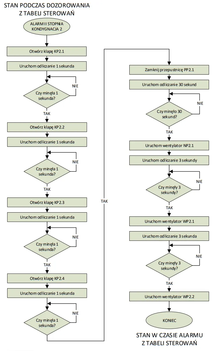
Improved control algorithm, accounting for power supply limitations
Additionally, the specialist must account for technical limitations — primarily regarding power supply. When a device is switched on, there may be a sudden spike in current draw (known as an inrush current), many times greater than the nominal current. Simultaneously starting multiple devices could trip overcurrent protections. Therefore, the specialist must modify the procedure so that devices start at small time intervals from each other.
Reverse Control
The transition of devices and systems from the fire alarm state back to the monitoring or standby state is called reverse control. Sometimes it may look similar to the fire alarm control (with reversed order of actions), but it often differs significantly, and the specialist must account for these differences.
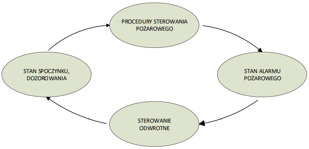
Fire control and reverse control
Control Matrix — Practical Implementation
The control matrix is the practical implementation of controls associated with the fire scenario adopted in the design, as described in the expert’s report and the control table. The matrix is stored in the non-volatile memory of devices (control panels) on site.
If controls are executed by a single control panel, we have an integrated matrix. If different panels are used, we have a distributed matrix.
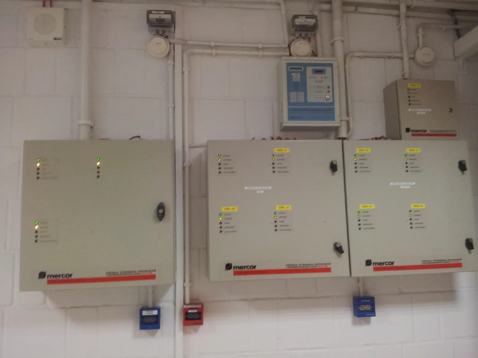
Multiple different control panels form a distributed control matrix
A challenge associated with the control matrix is documentation difficulty. Not all control panels allow their configuration to be saved as a verifiable document — often it is a binary file that can only be verified using configuration software. Some panels are configured directly using a built-in keypad and display, or even at the hardware level using jumpers and switches.

Building Users — Fire Safety Instructions
The user, owner, or manager of the building is obliged to develop and implement fire safety instructions containing, among others:
- fire protection conditions resulting from the building’s purpose and use,
- specification of required fire protection equipment and extinguishers,
- procedures in case of fire and other hazards,
- methods for securing fire-hazardous work,
- conditions and organization of personnel evacuation,
- methods for familiarizing building users with fire protection regulations,
- tasks and responsibilities regarding fire protection,
- building plans including data on fire zones, evacuation routes, and equipment locations,
- identification of persons or entities that prepared the instructions.
The fire safety instructions are essentially an implementation of the fire scenario at the level of ongoing building maintenance. The main emphasis is on fire alarm response procedures, evacuation procedures, and maintenance requirements for fire protection systems.
It is important to remember that fire safety instructions should be evaluated and updated at least every two years to reflect the current state of the building. This means that the fire scenario is not created once and for all — it evolves with the building throughout its entire service life.
Monitoring Fire Scenario Implementation
Technological development brings new tools that can be used to improve fire safety in buildings. These include various hardware-software platforms for visualization and control that can work with fire protection systems.
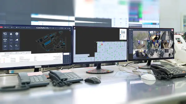
In Poland, such devices are Fire Protection Device Integration Systems (SIUP), consisting of dedicated hardware (typically an industrial computer) and software. Built on a client-server architecture, they include both an integration device and operator workstations.
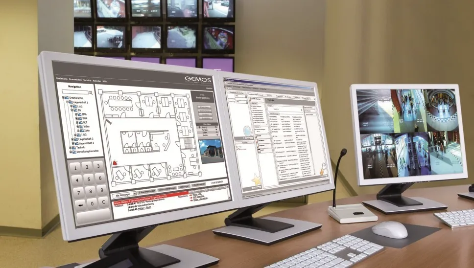
Fire Protection Device Integration System operator station
The integration system can be used to monitor the fire scenario at many stages of a building’s lifecycle:
- During construction and installation — it helps track whether control matrices are correctly programmed and whether all devices respond to fire alarms according to the scenario.
- During ongoing operation — it supports maintenance oversight by monitoring system condition and faults, reporting detected errors, and overseeing maintenance schedules.
- During a fire alarm — it guides operators through actions required by the scenario, logs their correct or incorrect execution, and confirms whether the scenario was implemented correctly.
At the integration system level, fire safety instructions and procedures related to building operation and fire response can be implemented. The system can guide operators through required actions or enforce diligent procedure compliance.
Summary
A fire scenario for a building can be viewed differently by different people — depending on whether they are participants in the construction process, involved in implementation, or building users. Therefore, the scenario can be described in different ways:
- expert’s report by the fire protection specialist,
- control table prepared by the designer,
- control matrix implemented by the fire automation specialist,
- fire safety instructions deployed by the building user.
The description may be more general, covering the entirety of the building’s fire safety, or focus on details that allow precise and reliable compliance with safety and technical requirements. In practice, none of these approaches is fully complete and exhaustive, but they are complementary and mutually reinforcing — only together do they form a complete description of the building’s fire scenario.